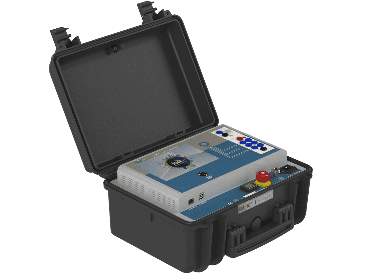
FULLY AUTOMATIC CT& VT TESTER
FULLY AUTOMATIC CT& VT TESTER
Introduction:
The iCT1 is a fully automatic test set specially designed for testing Current Transformers (CTs), Voltage Transformers (VTs), and Combined Transformers. Featuring an innovative 5-TAP switchbox, the iCT1 significantly reduces testing time by allowing up to five taps to be connected directly. This means the device needs to be connected only once, eliminating the need for additional manual operations during testing. The iCT1 performs all major transformer tests in fully automatic mode, without user intervention, including: Excitation (Saturation) Test, Accuracy Test, Ratio and Phase Error Test, Winding Resistance Test, Burden Test.
All tests are performed by generating the required current and voltage, ensuring reliable and accurate measurements. The system is operated through a 7-inch colour LCD touchscreen, specifically designed for use in outdoor environments. Test results can be stored in the instrument's internal memory or transferred to a USB flash drive. Settings and test results can also be transferred to a PC via an Ethernet connection, either wired or wireless.
Application:
The iCT1 is ideally suited for both factory testing and commissioning applications.
Key advantages include:-
- Testing in accordance with applicable international standards
- High-accuracy testing of CTs up to Class 0.1
- Significant time savings for faster production and testing cycles
- One instrument for testing CTs, VTs, and Combined Transformers
- Capability to test Current Transformers with very high saturation voltages, up to 30 kV
- Compact and easy-to-carry design, suitable for field and commissioning applications
- Fully automatic test execution with minimal operator intervention
The iCT1 combines speed, accuracy, automation and portability, making it an efficient solution for transformer testing in both manufacturing and field environments.
Current Transformer Test:
Turn Ratio and Polarity Voltage Mode
The ratio measurement is performed applying High Voltage AC to the CT secondary side, and measuring the CT primary voltage.
Burden Secondary Side
The burden measurement is performed applying low AC current to the CT burden, and measuring the voltage drop. . Excitation Curve (Knee Point)
The excitation curve is tested in two di erent methods: • Standard Method: it is connected the high AC voltage output to the CT secondary side, slewing the voltage and measuring at the same time the output voltage and current. • DC Method: it is connected the low DC voltage generator to the CT secondary side, varying the voltage and measuring at the same time the output voltage and current. The DC voltage allows to saturate the CT core, then the Knee voltage is calculated at the nominal frequency.
Winding Resistance
The resistance is measured connecting the low DC current source to the winding or burden, and measuring the test current and the voltage drop.
ALF / ISF
Purpose of the test is to calculate the ALF/ISF value using the Winding Resistance test results and the Burden Secondary Side test results. ALF = Accuracy Limit Factor and ISF = Instrument Security Factor.
Leakage Current
The test is performed connecting the high AC voltage source between the CT primary and secondary windings, and measuring the leakage current.
Accuracy
The Accuracy test verifies automatically the CT characteristics (ratio error and phase error) according to the standards, typically at 120%, 100%, 20%, 5% and 1% of rated current.
Demagnetizer
Purpose of this procedure is to apply a DC current with alternate polarity to the winding, in order to remove from the core the residual magnetism due to a previous winding resistance measurement.
CT Explorer
Sometimes the nameplate is not easy to be read or can be missing. Which nominal parameters have to be used in the test? iCT1 implements the CT Explorer functionality: from test results, thanks to the evaluation of the data, it is able to detect the most important nameplate data of the CT.
Voltage Transformer Test:
Ratio
The ratio measurement is performed by applying high voltage to the VT primary, and measuring the VT secondary voltage.
Ratio Electronics
The ratio measurement is performed applying high voltage to the VT primary side, and measuring the low-level VT secondary voltage.
Burden
The burden measurement is performed applying low AC voltage to the VT burden, and measuring the corresponding current.
Leakage Current
The test is performed connecting the high AC voltage source between the VT primary and secondary windings, and measuring the leakage current.
Technical Parameters:
Main generator
The main generator has 5 outputs: • High AC voltage • Low AC current • Low DC current • Low AC voltage • Low voltage for DC method test
High AC voltage
• MAX Voltage 2000 V • MAX Current 1 A
Low AC current
• Imax 6A AC • Vmax 100V AC • Max Power 200VA
Low DC current
• Imax 6A DC • Vmax 30V DC • Max Power 180W
Low AC voltage
• Maximum output voltage: 180V AC • Maximum output current: 3.5A AC • Maximum output power: - Supply 230V : 400 VA (Power values with cosj< 0.225) - Supply 110V : 350VA (Power values with cosj< 0.175)
Low voltage for excitation curve DC method
• Maximum output voltage: 200V DC • Maximum output current: 2Arms, 15A peak
Output frequency • Frequency: 15Hz – 400Hz • Frequency resolution: 10mHz • Frequency accuracy: < 100 ppM; output voltage > 200 V
Other features of main outputs
• Zero crossing control: the generation starts and stops on the zero crossing • Over-current: alarm message • Thermal protection for: Power supply, Power amplifier, Power transformer. The operator is alerted by a message.
Input AC Current: 0.1A to 10A
Input DC Current: 0.15A to 15A
AC Voltage Primary Side: 300mV to 300V
AC Voltage Secondary Side: 2V to 2100V
DC Voltage: 20Mv to 200V
Available Models: iCT1
Product Link: https://www.doble.com/product/ict1/