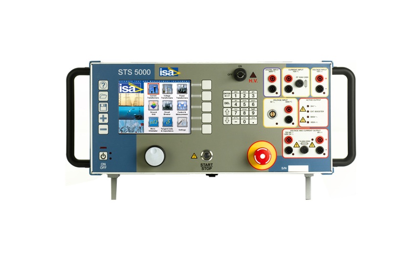
MULTIFUNCTION SUBSTATION TEST SET
MULTIFUNCTION SUBSTATION TEST SET
Introduction:
STS 5000 is a multifunction substation maintenance & commissioning test system for current, voltage and power transformers designed to perform primary tests requested in substations commissioning. It allows to perform accurate tests on CTs, VTs, PTs and ground grid.
The STS family includes 4 models: STS 5000, STS 4000, STS 3000 light and TDX 5000. STS 5000 is not equipped with: AC and DC high current outputs. STS 3000 light is not equipped with: AC and DC high current outputs, AC and DC high and low voltage outputs, and current and voltage meters. All models can be connected to the Tan Delta module TD 5000; STS 5000 and STS 4000 can be connected to the very high current module BUX 5000, BUX 3000 and BUX 2000. STS 5000 includes six output generators: high AC current; low AC current; high DC current; low DC current; high AC voltage; low AC voltage. In the local control mode, the selected output is adjustable and metered on the large, graphic LCD display. With the control knob and the LCD display, it is possible to enter the MENU mode, that allows to set many functions, that make STS 5000 a very powerful testing device, with manual and automatic testing capabilities, and with the possibility to transfer test results to a PC via ETHERNET or Pen Drive. The TDMS software, which comes with the test set, allows to download, display and analyze test results obtained in local mode. Remote maintenance and diagnostic of the instrument is available via Ethernet. TDMS operates with all Windows® versions. The ease of operation has been the fi rst goal of STS 5000. This is why the LCD display is so large and the dialogue in MENU mode is made easy. Connection diagrams are available according with the test window. STS 5000 includes three measurement inputs: • DC voltage (10 V DC) • AC voltage: - High range (300 V AC) - Low range (3 V AC) • Current (10 A AC or DC) All these inputs are independent among them and allow the measurement of CT or VT outputs or of another source.
IEC 61850-9-2 Sampled Values
STS 5000 has the facility to test CT, VT, both conventional and non-conventional, Merging Unit (MU) using the IEC 61850-9-2 (SV) protocol. The STS 5000 generates current or voltage signal and injects these quantities into the CT or VT under test. The STS 5000 then reads the data from the network (Sample Values) in order to perform a variety of different tests. • Possibility to test CT ratio and polarity check up to 2000 A (with BUX 2000 ), 3000 A (with BUX 3000) or 5000/ 7000 A (with BUX 5000) • Possibility to test VT ratio and polarity up to 2 kV • Test of MU
Test of Current Transformer:
CT Ratio and Polarity Voltage Method
The ratio measurement is performed applying high-voltage AC to the CT secondary and measuring the CT primary voltage. Input parameters are: the nominal primary and secondary current, from which the program computes the nominal ratio, the voltage range, the nominal test voltage and the test frequency. The display shows: • The voltage output, the secondary voltage and the current during the test • Actual ratio and ratio error • Phase shift and polarity.
CT Ratio and Burden Current Method
The ratio measurement is performed applying high current to the CT primary and measuring the CT secondary current. The burden can be by-passed or left in series for the measurement. In this instance, the voltage drop is measured. The secondary current can be measured by a clamp. Input parameters are: the nominal primary and secondary current, from which the program computes the nominal ratio and the nominal test current. The display shows: • The actual primary current • The corresponding secondary current • The value of the secondary current with the nominal primary current • Actual ratio and ratio error • Phase shift and polarity When the burden is tested, the following parameters are displayed: • The voltage drop across the burden • For the burden: VA rating at the nominal current, angle and power factor.
CT Burden Secondary Side
The burden measurement is performed applying low AC current to the CT burden and measuring the voltage drop. Input parameters are: the nominal secondary current and the nominal test current. The display shows: • The actual current output • The voltage drop across the burden • For the burden: VA rating at the nominal current, angle, and power factor • The actual ALF/ISF
CT Excitation Curve
The excitation curve is tested connecting the high AC voltage to the CT secondary, ramping the voltage and measuring at the meantime the output current and voltage. Input parameters are taken from the CT nominal value window. Other inputs are: maximum test voltage, maximum current and test frequency. The test set controls the output voltage and current during the test and stops as the knee is recognized. The display shows: • The characteristic curve • The actual voltage knee and the error with respect to the nominal • The actual current error at knee.
Winding Resistance
The resistance (not impedance) is measured connecting the low DC current source to the winding or burden, and measuring the test current and the voltage drop. Input parameters are: the nominal resistance, the connected output, the test current and the resistance limits. It is also possible to compensate the test temperature. The test set controls the output current and voltage during the test, and stops as the test current is reached. The display shows: • The test current • The voltage drop • The measured resistance and the compensated resistance • The test duration and the current deviation when the measurement was achieved.
Voltage Withstand
The test is performed connecting the high AC voltage source between the CT secondary cabling and the ground. Input parameters are: maximum test current (with automatic switch-off), test time, output range, test voltage, test frequency. The display shows: • During the HV ramping, the test voltage and current • As the test is completed, the maximum current, the total elapsed time and the isolation impedance.
Rogowski Coil
The test is performed connecting the high AC current course to the primary side, and connecting the CT secondary side to the low voltage measurement. Input parameters are: the nominal primary current and the nominal secondary voltage, from which the program computes the nominal ratio, the current range, the test current and the test frequency. • The range current and the test current • The actual test current, the secondary voltage and the value of the primary current with the nominal secondary voltage • Actual ratio and ratio error • Phase shift and polarity.
Low Power
The test is performed connecting the high AC current source to the primary side and connecting the CT secondary side to the lowvoltage measurement. Input parameters are: the nominal primary current and the nominal secondary voltage, from which the program computes the nominal ratio, the current range, the test current and the test frequency. The display shows: • The range current and the test current • The actual test current, the secondary voltage and the value of the primary current with the nominal secondary voltage • Actual ratio and ratio error • Phase shift and polarity.
Remote Polarity Check
The test is performed generating a special AC current waveform on the primary side and measuring the secondary current drop, with the optional PLCK polarity checker. Input parameters are: the test current, the time interval and the test result (Pass/Fail). The display shows the test current and records the test result of the different points.
Power Factor, Capacitance and Tan Delta
The test is performed using the TD 5000 optional module, and then connecting the high AC voltage source to test target. Input parameters are: Winding, test voltage and frequency, test mode, and the nominal capacitance, PF, DF. The display shows the following data: • Test voltage, current and frequency • Capacitance, Tan Delta and power factor • Power data: active, reactive, and apparent • Impedance: module, argument, and components.
Test Of Voltage Transformer:
VT Ratio and Polarity
The ratio measurement is performed applying high voltage to the VT primary and measuring the VT secondary voltage. Input parameters are: the nominal primary and secondary voltage, from which the program computes the nominal ratio, type of connection (Y or Delta), the HV range, the nominal test voltage and frequency and the selected voltage meter. The display shows: • The actual test voltage • The secondary voltage • The Value of the secondary voltage with the nominal primary voltage • Actual ratio and ratio error • Phase shift and polarity.
VT Burden
The burden measurement is performed applying low AC voltage to the VT burden and measuring the corresponding current. Input parameters are: the nominal secondary voltage, the voltage range, the test voltage and frequency. The display shows: • The actual voltage output • The output current • For the burden: VA rating at the nominal voltage, angle, and power factor.
Ratio of Electronic Transformer
The ratio measurement is performed applying high voltage to the VT primary, and measuring the low-level VT secondary voltage. Input parameters are: the nominal primary and secondary voltage, from which the program computes the nominal ratio, type of connection (Y or Delta), the HV range, the nominal test voltage and frequency. The display shows: • The actual test voltage • The secondary voltage • The value of the secondary voltage with the nominal primary voltage • Actual ratio and ratio error • Phase shift and polarity.
Voltage Withstand
The test is performed connecting the high AC voltage between the VT secondary cabling and the ground. Input parameters are: maximum test current (with automatic switch off), test time, output range, test voltage and test frequency. The display shows: • During the HV ramping, the test voltage and current • As the test is completed, the maximum current, the total elapsed time, and the isolation impedance.
Remote Polarity Check
The test is performed connecting the high AC voltage source to the primary side and measuring the secondary voltage, with the optional PLCK polarity sensor. Input parameters are: the test current, the time interval and the test result (Pass/Fail). The display shows the test current and records the test result of the different points.
Power Factor, Capacitance, and Tan Delta
The test is performed using the TD 5000 optional module, and then connecting the high AC voltage source to test target. Input parameters are: Winding, test voltage and frequency, test mode, and the nominal capacitance, PF, DF. The display shows the following data: • Test voltage, current and frequency • Capacitance, Tan Delta and power factor • Power data: active, reactive, and apparent • Impedance: module, argument, and components.
Test of Power Transformer:
Ratio per TAP
The ratio measurement is performed applying high voltage to the PT primary and measuring the PT secondary voltage for each tap. If the option STCS or STCS PLUS is available, connection is performed via the option and the test is completely automatic. Input parameters are: the nominal primary and secondary voltage, from which the program computes the nominal ratio, type of connection (Y or Delta), the type of Tap changer, the HV range, the nominal test voltage and frequency and the selected voltage meter. The display shows: • The test current and angle • The test voltage, primary, and secondary • Actual ratio and ratio error • Phase shift and polarity.
Vector Group
The test is performed connecting the high AC voltage source between PT primary windings, while the others are short-circuited. The test is composed by two measures of secondary windings voltage and phase shift. If the STCS option is available, connection is performed via the option and the test is completely automatic. Input parameters are: the test voltage and frequency, the nominal turn ratio, the presence of neutral winding. The display shows: • Test voltage and frequency • Test connections • Phase displacement and connection.
Static and Dynamic Winding Resistance and TAP Changer Test
The test is performed applying DC current to the PT primary plus Tap Changer and measuring the voltage drop. The tester measures the resistance peak during the switch and the resistance after the selection. If the option STCS or STCS PLUS is available, the connection is performed via the option and the test is completely automatic. Input parameters are: the tap number, the type of Tap Changer, the current range, the test current, the nominal resistance and the resistance limits. It is also possible to compensate the test temperature. The test set controls the output current during the test and issues the Tap Change command. The display shows: • The test current • The tap number • For the static resistance: the test voltage and resistance, also compensated • For the dynamic resistance: the measured values are the Ripple and the Slope and a graphical representation of current and resistance profi les. The dynamic resistance measurement is performed also without the STCS or STCS PLUS option.
No-Load Current
The test is performed using TD 5000 optional module or using the internal high voltage source up to 2kV and then connecting the high AC voltage source to the test target. Input parameters are: the tap number, the type of Tap Changer, the test voltage and the frequency. The test set applies the high voltage and measures the output current during the test. The display shows: • The test voltage • The current and the phase shift • The power losses • The reactance.
Short-Circuit Impedance
The test is performed applying low AC current to the winding under test, while the other windings are short-circuited and measuring the associated voltage and phase shift. Input parameters are: the test current and frequency, the type of winding and the phase under test. It is also possible to compensate the test temperature. The test set measures the output voltage and computes the related parameters. The display shows: • Phase shift; the power loss; the R, X, Z and inductance of the transformer • Short-circuit impedance in Per Unit.
Power Factor, Capacitance and Tan Delta
The test is performed using the TD 5000 optional module, and then connecting the high AC voltage source to test target. Input parameters are: Winding, test voltage and frequency, test mode, and the nominal capacitance, PF, DF. The display shows the following data: • Test voltage, current and frequency • Capacitance, Tan Delta and power factor • Power data: active, reactive, and apparent • Impedance: module, argument, and components.
Breaker and Relay Testing:
CB - Primary and Secondary Relay Tests
The selection allows to inject the test parameter and measuring the relay threshold and trip delay of a breaker or of a relay. It is also possible to measure external voltages and currents. With the option BUX 5000 it is possible to perform high current tests, up to 7000 A. Input parameters are: current range, output current, output voltage and frequency. It is possible to enable the time measurement on the digital input or on the fall of the applied current (breaker tests) and to set the type of digital input (wet or dry). The display shows the following data: • Test current or test voltage • Trip time • Closing time • External voltage and current measurements.
Circuit Breaker Testing:
Contact Resistance
The contact resistance test is performed using the high DC current output. The test set measures the contact resistance down to the µOhm range. With the same selection it is also possible to measure higher resistances. Input parameters are: current output range, test current and resistance limits. The display shows: • DC current • DC voltage • Resistance.
Power Factor, Capacitance and Tan Delta
The test is performed using the TD 5000 optional module, and then connecting the high AC voltage source to test target. Input parameters are: Winding, test voltage and frequency, test mode, and the nominal capacitance, PF, DF. The display shows the following data: • Test voltage, current and frequency • Capacitance, Tan Delta and power factor • Power data: active, reactive, and apparent • Impedance: module, argument, and components.
Ground Grid Testing:
Ground Grid Impedance
The test of ground grid impedance is performed applying current between the ground grid and the auxiliary ground spikes. With the STLG option the test is performed using an overhead line to connect to the remote ground. For the impedance test, input parameters are: output voltage range, test current, test frequency. The display shows: • Test Probe Distance • Output Voltage • Test Probe Voltage • Output Current • Phase Shift • Earth Impedance • Evaluation.
Step and Touch Voltages
The step and touch voltages test is performed applying current between the ground grid and the auxiliary ground spikes and measuring the step or touch voltage with the test probes. With the STLG option, the current generation is performed using an overhead line to connect to the remote ground. Thanks to the STLG option, higher test current can be achieved. Input parameters are: substation fault current, fault clearance time, parallel resistance on the test probes. Other selections are: output voltage range, test current, test frequency. Last, the operator selects the measurement mode: manual or on STS and the reference standard. The display shows the following data: test current, location description, location coordinates, measured voltage, voltage in case of actual fault.
Soil Resistivity
The test of soil resistivity is performed applying AC voltage to the current spikes and measuring the injected current and the voltage across the voltage spikes. For the resistivity test, input parameters are: voltage range, test current, test frequency. The display shows: • Location • Probes Distance • Output Voltage • Voltage between Probes • Output Current • Corresponding Resistivity • Evaluation.
Line Impedance Measurement:
Line Impedance
The line impedance test has the purpose of verifying the computed value of the Earth coeffi cient KL for the HV overhead lines. This is a critical parameter for the setting of a distance relay: a wrong value causes the false fault location. The test is performed injecting current into the lines, in many modes: line to line, three lines to ground, with or without current in parallel lines. With the STLG option, the current generation can be performed even in presence of induced voltages. The device measures the injected current and the corresponding voltage drop and phase shift. Input parameters are: maximum test voltage and test current. Other parameters are the line material and the test temperature. Tests are performed at frequencies ± 5 Hz with respect to the line frequency, in order to remove the noise. To the left, the display shows the measured and computed values of the impedances; to the right, the computed corrective factors.
Available Models: STS-5000, STS-4000, STS-3000
Product Link: https://www.doble.com/product/sts-5000/